 |
Firmware for the RF Signal Generator [0410619A.HEX]
ATmega328P microcontroller firmware (HEX file) and BASIC source code for the AM/FM/CW Scanning HF/VHF RF Signal Generator (0410619A.HEX).
Update: this new version (V14) suits both pulse-type and level-type rotary encoders. You can identify a pulse type encoder as the two internal switches are always open when the encoder is at rest, while a level-type encoder will have one or both switches closed in some rotational positions. If your encoder is a level-type, solder a 100kΩ resistor from pin 28 of IC1 to GND to enable correct operation.
|
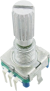 |
Pulse-type rotary encoder with pushbutton and 18t spline shaft
A five-pin rotary encoder with two mounting tabs that has been confirmed as the pulse type. Suitable for use in several projects published in the magazine (see below).
|
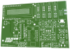 |
AM/FM/CW Scanning HF/VHF RF Signal Generator PCB [04106191]
The PCB for the RF Signal Generator from the June & July 2019 issues.
Double-sided PCB with plated through holes, solder mask and silkscreen overlay.
152.5 x 101.5mm.
|
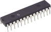 |
ATmega328P programmed with the firmware for the RF Signal Generator [0410619A.HEX] (V14)
An ATmega328 8-bit microcontroller programmed with the firmware for the AM/FM/CW Scanning HF/VHF RF Signal Generator (0410619A.HEX).
Update: this new version (V14) suits both pulse-type and level-type rotary encoders. You can identify a pulse type encoder as the two internal switches are always open when the encoder is at rest, while a level-type encoder will have one or both switches closed in some rotational positions. If your encoder is a level-type, solder a 100kΩ resistor from pin 28 of IC1 to GND to enable correct operation.
|
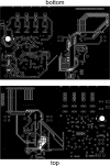 |
AM/FM/CW Scanning HF/VHF RF Signal Generator PCB pattern (PDF download) [05105191]
PDF with the PCB design for the RF Signal Generator (double-sided).
This would be difficult to etch yourself, so it's provided mainly as a reference.
Both layers are in a single PDF.
|
 |
AM/FM/CW Scanning HF/VHF RF Signal Generator panel artwork, cutting diagrams and STL files (downloads)
PDFs with the panel artwork and cutting/drilling diagrams for the RF Signal Generator. The STL files for 3D printing the knobs are also availble in a separate ZIP.
These files have been revised to fit the following problems:
1) missing width on cover cutting diagram
2) panel artwork was not drawn to the correct scale
3) the base cutting diagram was the wrong side (150mm wide instead of 105mm)
|